


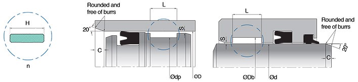
- It should be paid to attention rod chamfer and bore chamfer angle, dimensions, and radius values that in seal groove and edge.
- In the selection of cylinder rod, products with an induction hardened surface up to 2.5 mm deep, at least 45 HRC hardness, and 25- 40 μm chrome plated at the point should be preferred. Hardness value; to be used 50-60 HRC may be required depending on the material of the sealing element, pressure values and working conditions.
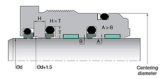
- Centering should be done between the throat wedge and pipe, rod and piston head. Depending on the cylinder diameters, centering should be done at H7/f7 or H8/f7 tolerances. Care must be taken to ensure that the parts concentricity to each other.
- Attention should be paid to oil inlet and outlet ports; design that do not create cavitation or turbulent flow should be applied.
- If metal guide rings are to be used, spiral oil channels must be produced in cutting process. Hydrodynamic pressure build-up should be avoided. The loads on the cylinder should be taken into consideration in the guide ring selection.
- Care should be taken to ensure that the static sealing slots are rectangular.
- In sealing element designs which is used in open grooves, precautions must be taken to anti loosening for screw on the piston head and rod assembly. Set screw and chemical fixing solutions for teeth are widely used in systems.
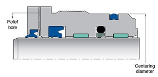
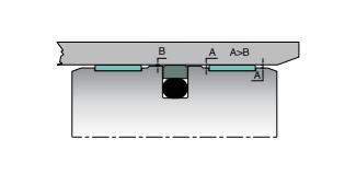
- If double-acting rod wiper or scraper is used, It is recommended to design an relief bore behind of the main sealing element. If the main sealing element does not have the relief feature, the relief bore must be opened. The extrusion gap «S» behind the main seal and the guide ring walls It is recommended to be manufactured in different dimensions (A-B). If piston designs with step by step without straight line (A>B) it will allow smooth oil relase and it will help to incrase efficient operation of the system.
- In tandem sealing designs, it is aimed to collect the oil in a wide area and increase the guide ring efficiency of the system by placing a guide ring between the 1st and 2nd sealing elements.
- If it is hard to pre-forming for the some products, for example; packings, seals that have high cross sections out of hard materials and diameter - cross section ratios higher than the values given in Table 3.2, spring energized PTFE products etc. It must be installed to splitted groove. Attention should be paid to ensure to concentricity between parts in rod and parts should be contact tightly and care to be taken produced without create to gap in the seal groove. At the same time, care should be taken to keep the parts fixed when used splitted groove, which is used under high pressure. Also it should be prevent the parts from losing contact; necessary precautions must be taken to prevent loosening screw.
Consideration on Hydraulic Cylinder Design
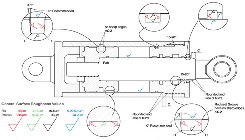
The values in the picture above are general values. Values may vary depending on the sealing element material and media type.
Recommended Chamfer Values for Hydraulic Cylinder «C»
| Wall thickness ≤ |
Cmin | Wall thickness ≤ |
Cmin |
| 2 | 2.5 | 14 | 19 |
| 3 | 3.5 | 15 | 9.5 |
| 4 | 4.5 | 16 | 10 |
| 5 | 5.5 | 17 | 11 |
| 6 | 5.5 | 18 | 11.5 |
| 7 | 5.5 | 19 | 12 |
| 8 | 6 | 20 | 12.5 |
| 9 | 6 | 21 | 13 |
| 10 | 6.5 | 22 | 14 |
| 11 | 7.5 | 23 | 14.5 |
| 12 | 8 | 24 | 15 |
| 13 | 8.5 | 25 | 15.5 |
Surface roughness values can affect greatly sealing element performance.
For this reason, before assembly, it is important to checking rod, bore surface and seal goove surface roughnes according to that are given catalouge values and it is recommended to check this values. (See page 60 - 61 - 62)
C values given in Table 3.3 on the side are appropriate chamfer values for installation of seals without damage There should be no sharp edges and burrs on the chamfer. All unspecified inside and outside edges fillets are set as r≤0.2.
Chamfer Angle: It should be in the range of 15-20°.
In tandem seal systems for "C" value, it is should be considered according to which seal have bigger cross section.
Surface Roughness Values
Surface roughness values of the mating surface where the sealing elements will work directly affect the performance or operating life of the sealing elements. Mating surfaces must be honed, grinded, burnished or polished. (Table 3.4) In addition, coating can be applied on the mate surface (chrome coating, ceramic coating, etc.). Surface roughness values should be in the value range given in Table 3.5 according to the type of sealing element.
The compatibility of the sealing elements with the mating surface roughness varies according to the type of material used. Elastomer materials adapt very well to changes in the work surface, thermoplastic materials adapt well, while PTFE materials cannot easily adapt to surface variations.
Suggested surface roughness values may vary depending on the rod material, fluid type (liquid, gas), viscosity values and surface coating material used in the system.
Please contact our sales department for application that require usage of different fluids.
It is very important to harden the rod before coating and polishing processes on the surfaces. Depending on the type of filling in filled PTFE types, different surface hardnesses are required especially in rotary applications.
| Surface Roughness Values of Mate Surface According to Sealing Material «μm» |
||
| Rod and Bore Surface | ||
| Parameter | PTFE | Elastomer-Thermoplastic |
| Ra | 0.05-0.2 | 0.1-0.4 |
| Rz | 0.40-1.60 | 0.6-2.50 |
| Rmaks | 0.60-2.50 | 1.0-4.00 |
| Rmr (Cref=%5 - Rz/4) | %60-%90 | %50-%70 (Thermoplastic) %55-%80 (elastomer ) |
Surface Roughness Compatibility
of Materials
NBR
PU
PTFE
| Surface Roughness Values According to Fluid Type | ||||
| Ra Values | ||||
| Application | Thermoplastic and Elastomer Seals |
PTFE Seals | ||
| Dynamic Surfaces |
Static Surfaces |
Dynamic Surfaces |
Static Surfaces |
|
| Cryogenics | - | - | 0.1 µm (maks) |
0.2 µm (maks) |
| Helium, Hydrogen, Freon (air conditioning refrigerant R22-R404) |
0.1-0.25 µm | 0.3 µm (maks) |
0.15 µm (maks) |
0.3 µm (maks) |
| Air, Nitrogen, Argon, Natural Gas, Fuels (Airplane and car) |
0.1-0.3 µm | 0.4 µm (maks) |
0.2 µm (maks) |
0.4µm (maks) |
| Water, Hydraulic oil, Crude oil |
0.1-0.4 µm | 0.8 µm (maks) |
0.3 µm (maks) |
0.8 µm (maks) |
| Rz Values | ||||
| Aplication | Thermoplasctic and Elastomer Seals | PTFE Seals | ||
| Dynamic Surfaces |
Static Surfaces | Dynamic Surfaces |
Static Surfaces |
|
| All Fluids |
Rz ≤ 8 x Ra 1.6 µm (maks) |
Rz ≤ 6 x Ra | Rz ≤ 8 x Ra 1.6 µm (maks) |
Rz ≤ 6 x Ra |
| Note: Rz values higher than the recommended maximum values will increase seal wear. | ||||
| Rz Values | ||||
| Aplication | Thermoplastic and Elastomer Seals |
PTFE Seals | ||
| Dynamic Surfaces |
Static Surfaces |
Dynamic Surfaces |
Static Surfaces |
|
| All Fluids | %50---%70 (thermoplastic) |
---- | %60-%90 | ---- |
| %55---%80 (elastomer) |
||||
| The value of Rmr should be viewed according to the points Rz / 4 and Cref = 5%. | ||||
Surface Roughness Values
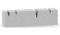
Ra – Absolute arithmetic mean value of the measurement points distance x to the centerline of the measurement profile.
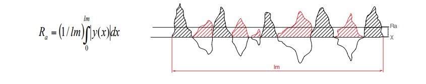
Calculation of Ra profile
Ra parameter does not differ according to the peak point or depth structure of the profiles (Picture 3.58).
Ra or any other parameter alone is not sufficient to determine the suitability of the surface. Surface roughness parameters should be evaluated as a whole and should comply with catalog values.
Ra=2.4 µm

Ra=2.5 µm
Ra=2.4 µm

Ra values of different profiles
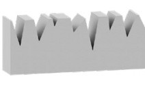
Rz - Average Surface Roughness Value:Arithmetic average of 5 Rz values in the measurement range.
Rmaks - Maximum Surface Roughness Depth: Largest of the 5 Rz values in the measurement range.
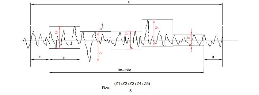
Calculation of Rz parameter and Rmax value
Surface Roughness Values
Rmr - Percentage of Material in Profile: Rmr is the percentage of material contact at a given depth in a profile surface measurement section. Surface contact area percentage Rmr is the ratio of surface roughnesses of a certain length of surface to the non-contacting surface when cutting at depth C. Kastaş takes the reference line Cref=5% in Rmr calculation and calculates the percentage of material contact in the Rz/4 section.
Ra and Rz parameters alone do not give sufficient information about the surface on which the sealing element will work. When these parameters are evaluated together with the Rmr value, the suitability of the work surface can be determined.
In order to obtain the appropriate Ra, Rz, Rmr values, attention should be paid to grinding on rods, honing on bores or special processes, and should be manufactured in accordance with catalog information.
Otherwise; if Rmr value approaches 0%, the peak value of the surfaces will be high and cause abrasive effect else Rmr value approaches 100% which will increase temperature values due to the lack of suitable oil film. Sealing elements might be deformed by high temperatures and oil leaks can be observed in low pressure systems with 100% Rmr value.
The percentage of material changes at different surface measurement section depths.
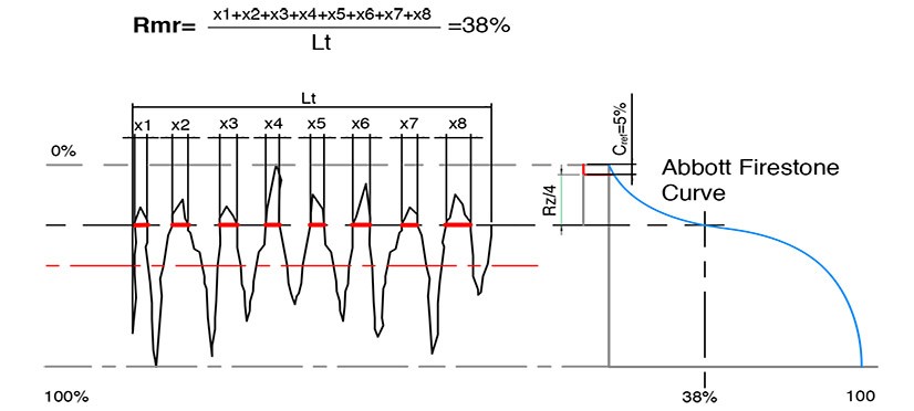
Calculation of Rmr value
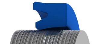
Extrusion Gap
Sealing elements work safely at certain pressures and certain extrusion gaps according to their materials and designs.
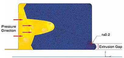
The extrusion gap value is expressed as the gap between the sealing element groove and the working surface (rod or bore). The high stress that occurs behind the sealing element in the pressure direction can cause the material to flow into extrusion gap behaving like a fluid under the effect of pressure.
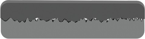
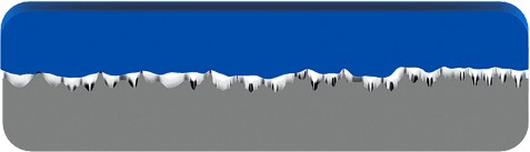
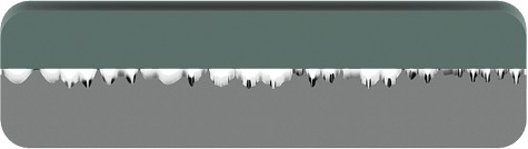
Picture 3.63 shows the extrusion rates of a sealing element at same pressure with different extrusion gaps.
Extrusion resistance varies depending on the temperature. As the temperature increases, mechanical properties of the materials decreases and extrusion gets easier. Especially in systems with temperature above 60 °C, the diameter values of the extrusion gap (calculated so that there is no metal-to-metal contact risk) may need to be reduced and increased according to the system conditions.
One of the most common faults in the systems is the elongation deformation seen behind the sealing element due to improper design of the extrusion gap or the increase in the extrusion value due to axial misalignment in the system. The extrusion gap value considered in the design may increase in the following cases. The maximum extrusion gap should be calculated taking these situations into account.
Factors Affecting Smax Value
- Axial misalignment depending on cylinder weight.
- The effect of external loads and depending on the type and operation of the cylinder assembly (operating at angled, horizontal condition, middle connection, rear connection) bending, tilting formation on the shaft.
- Gaps due to cross section tolerances of guiding elements and squeeze of guiding elements
- Clearances caused by manufacturing tolerances of cylinder parts.
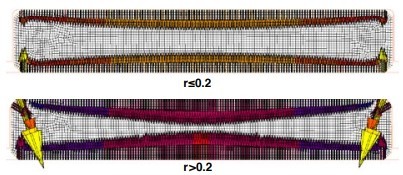
One of the most important things to be considered in groove manufacturing is the radius behind the sealing element. For double acting sealing elements, both corners should have R≤0.2 mm. R values greater than 0.2 mm increases extrusion tendency.
Sealing Element SEA under 150 Bar Pressure
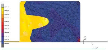
S=0.1 mm
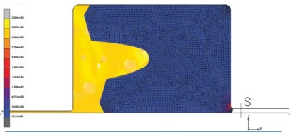
S=0.3 mm
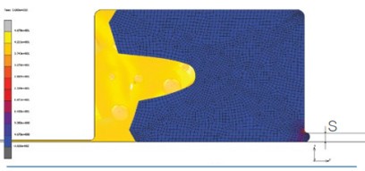
S=0.5 mm
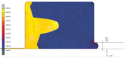
S=1 mm
Calculation of Rod and Piston Extrusion Gap Values
Guide ring grooves, guide ring cross section tolerances should be considered while calculating Smax and Smin values as stated below. Smax and Smin are critical values; while Smax directly affects the
extrusion of material, Smin value indicates the risk of metal to metal contact. Please contact our sales department if the Smin value is lower than 0.15 mm.
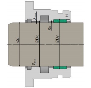
Gland - Rod Extrusion Gap
Gland - Rod Extrusion Gap Values
| Smaks | Maximum extrusion gap |
| Smin | Minimum extrusion gap |
| Sb | Guiding Gap |
| Ød | Rod diameter |
| ØDy | Guide ring groove diameter |
| ØDk | Diameter of sealing element extrusion gap |
| H | Cross section thickness of guide ring |
| Smaks | [(Dkmax-Ødmin)/2]+[Sbmax/2] |
| Smin | [ØDk-(ØDymax-(2*Hmin))]/2 |
| Sbmaks | [ØDymax-(2*Hmin)]-Ødmin |
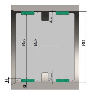
Piston Head - Bore Extrusion Gap
Piston Head - Bore Extrusion Gap Values
| Smax | Maximum extrusion gap |
| Smin | Minimum extrusion gap |
| Sb | Guiding Gap |
| Ød | Bore diameter |
| ØDy | Guide ring groove diameter |
| ØDk | Diameter of sealing element extrusion gap |
| H | Cross section thickness of guide ring |
| Smax | [(ØDmax-Ødkmin)/2]+[Sbmax/2] |
| Smin | [(Ødymin+(2*Hmin))] - (Ødkmax/2) |
| Sbmax | ØDmax-[Ødymin+(2*Hmin)] |
Guiding Elements
Although the guidings in the cylinders do not serve as sealing elements, they are the elements that directly affect the sealing performance. Guiding elements are used to carry the vertical loads on the cylinders and to prevent metal-to-metal contact. Systems should be selected considering stroke, working positions, speed and temperature values.
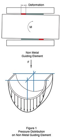
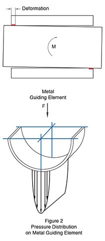
Most of today's systems use thermoplastic, PTFE, composite guiding elements instead of metal guiding elements.
- Easy to assemble, easy to replace in maintenance, low-cost solution
- High load carrying capacity
- High wear resistance and long life
- Ability to dampen vibrating systems
- Low friction
- Doesn’t create hydrodynamic pressure
- Works without damaging metal surfaces
Guiding Element Materials
Thermoplastic Guiding Elements: POM or PA guiding elements are generally used as glass fiber reinforced or pure. POM and PA bearing elements are preferred because they are economical. At temperatures of 60 °C and above POM and PA guiding elements load carrying capacity and surface contact pressure decreases as in other thermoplastics. They are suitable for use in light and medium duty applications.
PTFE Guiding Elements: PTFE guiding elements are used in systems where high temperature, chemicals exist in the working environment and low friction forces are required. Properties of PTFE guiding elements; bronze, carbon and molybdenum disulfide additives can be used to make guiding elements more suitable for the system they will work in. Good elasticity properties of PTFE guiding elements are the main choice reasons for designs. In some applications, PTFE guiding elements are used with other guiding elements with higher load carrying capacity. In such applications, PTFE guiding element collects foreign particles in the environment and prevents these particles from sticking to the harder guiding element and damaging the cylinder or rod. They are used in light and medium duty applications due to low contact pressures.
Composite Guiding Elements: They are products that are composed of a combination of cloths such as cotton, polyester, aramid etc., resins and different filling materials. They have high load carrying capacities and can be used in heavy-duty applications. Composite guiding elements create a much better bearing area thanks to their elastic structure; thus, it is more successful in carrying the radial forces in the system. Load distribution is close to homogeneous in the composite guiding elements, in this manner they prevent the problems caused by dry running because of misalignments in the system that may occur due to high elastic deformations. Resin prevents break apart of pieces from guiding elements. PTFE additive in composite guiding elements reduce friction. Composite guiding elements maintain their dimensional stability at high operating temperatures very well compared to other guiding elements. Nowadays, the load carrying capacities of the guiding elements, which are mostly preferred in the sectors where medium and heavy duty cylinders are used, changes with the effect of temperature and speed. Load carrying capacity decreases as temperature and speed increase.
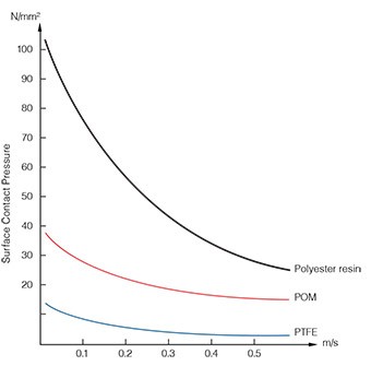
Surface Contact Pressure – Speed Graph at 60°C
Selection of Guiding Element
Guiding element calculation is very important in cylinders. During the design phase, calculations should be made according to information such as loads on the cylinder, cylinder operating position and stroke, and the most suitable products should be selected. Otherwise, the system may not operate safely and mechanical deformations may occur. Bearing length can be calculated according to the force that affects the bearing with the information given below.
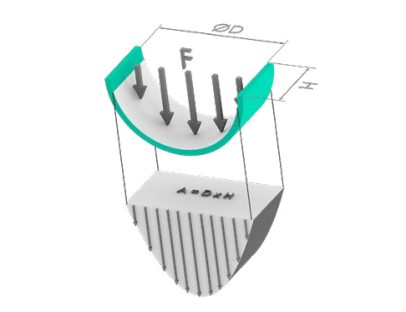
Guiding Element Load Calculation
- A: Total theoretical area affected by the force
- ØD: Bore diameter for piston, shaft diameter for rod
- H: Width of guiding element
- E: Safety factor
- Y: Load bearing capacity of guiding element (N/mm2)
- F: Force acting on guiding element
The formula to be used for choosing the most suitable guiding element width is given below. Force affecting the bearing must be known to use the formula.
Note: Force changes, speed and temperature values that may occur in the system should be taken into consideration while calculating the guiding element load carrying capacity. For this reason, it is recommended to take the "E" safety coefficient as at least 2.
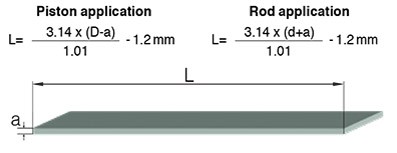
Strip Length Calculation of Guiding Bands
L= Length of guiding band (mm)
D= Nominal diameter of bore (mm)
d= Nominal diameter of shaft (mm)
a= Wall thickness of guiding element (mm)
Groove Information of Guiding Elements
Groove processing diameter tolerances in guiding elements are given with narrower tolerances than sealing elements. Measuring errors to be made in the guide ring grooves can have a significant effect on the system performance by directly affecting the "S" flow gap. It is important to make machining and check the dimensions by paying attention to the machining tolerances given in the catalog. Making the groove corner radius over the given value of r≤0.2 mm in the guide elements may cause problems during assembly and operation.
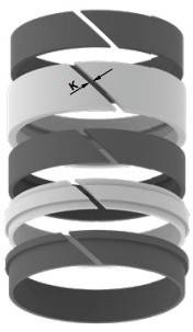
Guiding Element «K» Gap
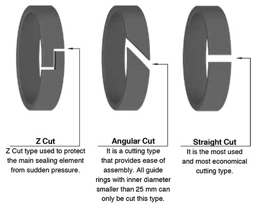
The gap called «K» range is of great importance in the bearings. This gap prevents the formation of hydrodynamic pressure by allowing the hydraulic fluid to reach the main sealing elements. Except special requests, it is recommended that the cutting angle of «K» range is 45 degrees. Cutting angle and type can be changed according to special requests.
«K» value range for thermoplastic and composite bearings can be seen in the table below.
| Ø | Composite Guide Ring min K |
Composite Guide Ring max K |
| Ø40 | 2.00 | 2.50 |
| Ø100 | 3.50 | 5.00 |
| Ø200 | 6.00 | 9.00 |
| Ø300 | 10.00 | 12.50 |
| Ø400 | 14.00 | 16.00 |
| Ø500 | 16.00 | 20.00 |
| Ø600 | 20.00 | 24.00 |
| Ø700 | 22.00 | 25.00 |
| Ø800 | 26.00 | 32.00 |
| Ø900 | 28.00 | 35.00 |
| Ø1000 | 32.00 | <38.00/td> |
| Ø | Thermoplastic Guide Ring «K» |
| 10-40 | 2-2.5 |
| >150 | 3-4 |
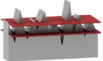
Guiding Element Types
Guiding elements can be manufactured in various designs. It can be produced in the form of «L», «U», «T» or flat depending on the applications and groove types they will be mounted on. «L» and «T» type bearings are generally seen in telescopic cylinder applications. They can be produced from glass fiber-reinforced thermoplastic materials. Load carrying capacities can be increased depending on the glass fiber additive.
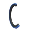
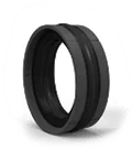
Guiding Element Profiles
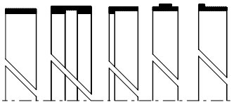
Guiding Element Cut Types